|
PicoLog 1012/1216 Meerdere Kanalen Logger |
 Ontworpen
om te voldoen aan de behoefte voor een wide range van
algemeen gebruik zoals voltage, sensor en transducer logging
applicaties: De "PicoLog 1000 meerdere kanalen data
acquisitie series" met onafhankelijke software en
configureerbare verschaling en control outputs maar ook een
extern terminal board voor custom front–end circuitry en de
keuze voor een 10– of 12–bit input resolution. Ontworpen
om te voldoen aan de behoefte voor een wide range van
algemeen gebruik zoals voltage, sensor en transducer logging
applicaties: De "PicoLog 1000 meerdere kanalen data
acquisitie series" met onafhankelijke software en
configureerbare verschaling en control outputs maar ook een
extern terminal board voor custom front–end circuitry en de
keuze voor een 10– of 12–bit input resolution.
•Up to 16 input channels per data logger
•Up to 4
output channels per data logger
•Use up to 4 data loggers
at the same time
•Up to 1 MS/s sample rate
•USB
connected and powered
•Data acquisition software and SDK
included
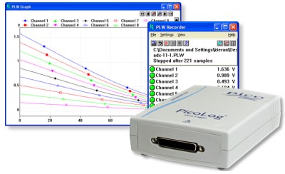
A distinguished pedigree
The PicoLog 1000 series is the result of a distinguished
lineage that goes back to the release of our first
multi–channel data logger — the ADC-11 — in 1993. The
original ADC-11, and its successor the USB ADC-11, proved to
be the perfect choice for users wanting a low–cost way to
measure and record multiple signals. The PicoLog 1000 series
builds on this success to give you the same low–cost data
acquisition but with greater power and performance. (Because
the ADC-11 was so popular we’ve also added a USB ADC-11
compatibility mode which allows you to use your PicoLog 1000
logger as a direct replacement to the USB ADC-11.)
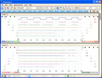
Use PicoScope to
view all 16 channels
 |
An expandable multi–channel data acquisition system
The budget model PicoLog 1012 has 12 input channels. The
powerful PicoLog 1216 has 16. Need more channels? No
problem. Using PicoLog you can connect up to 4 Pico data
loggers to one PC — giving you a potential 64 channel
PicoLog 1000 series data acquisition system, or the ability
to use your PicoLog 1000 logger with other devices such as
the USB TC-08 Thermocouple Data Logger.
Fast
and accurate
With 10– or 12–bit resolution and
multiple sampling modes, a PicoLog 1000 series logger will
meet your data logging needs. The PicoLog 1000 series has 3
sampling modes: Streaming mode allows channel voltage
readings to be logged continuously at up to 100 kS/s, while
block mode captures up to the full 1 MS/s sample rate of the
logger for a duration limited by the 8000 sample buffer,
both these speeds applying to single–channel operation. The
PicoLog application provides an extra mode, real–time
continuous sampling, which provides averaged, time–accurate
readings with automatic measurements at up to 1 kS/s on any
number of channels.
Control alarms and other
devices
The PicoScope 1000 series data loggers
include digital outputs — including one with pulse–width
modulation control (PicoLog 1216 only). These outputs can be
used to control alarms or other devices, additionally these
can also be used to power sensors such as thermistors.
 It’s
all you need It’s
all you need
Your PicoLog 1000 series
multi–channel data acquisition (DAQ) device includes all you
need to start measuring and recording. A full suite of
software is included in the price and consists of PicoLog
data logging package, the PicoScope oscilloscope package —
which provides measurement capabilities while allowing you
to view all 16 channels at once — and an SDK for using the
PicoLog 1000 within your own software, or third party
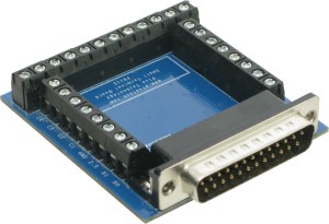
software such as LabVIEW. Additionally, an optional terminal
board with screw terminals lets you easily and quickly
connect your sensors to the logger. The board also has
solder pads on which you can fit resistors to widen the
measuring range for each input.
Easy to use. Low
cost. The PicoLog 1000 series is what you need
With
great performance and versatility, up to 16 inputs and 4
outputs per unit, a low per–channel cost and easy to use
features, the PicoLog 1000 series is the multi–channel data
acquisition device that you need.
Specifications
|
Inputs |
|
Model |
PicoLog 1012 |
PicoLog 1216 |
Maximum sampling rate
Continuous streaming
Real–time
continuous
Block mode#1
|
1 kS/s per channel in PicoLog, 100 kS/s
shared by all channels using the supplied
SDK
1 kS/s or greater
1 MS/s
single–channel |
|
Buffer memory |
8000 samples, shared by all channels |
|
Analog inputs |
12#2 |
16#2 |
|
Analog bandwidth (-3 dB) |
DC to 70 kHz |
|
Input type |
Single–ended, unipolar |
|
Input voltage range |
0 to +2.5 V |
|
Linearity (at 25 °C) |
1 LSB |
|
Resolution |
10 bits |
12 bits |
|
Accuracy |
1% |
0.5% |
|
Overload protection |
±30 V to ground |
|
Input coupling |
DC |
|
Input impedance |
1 MΩ |
|
Outputs |
|
Digital output (D0…D3) |
2 |
4#2 |
Digital outputs (PWM)
period
duty cycle
|
None |
1
100 µs to 1800 µs
Adjustable
from 0% to 100% in 1% steps |
Digital outputs (all)
logic low voltage
logic high voltage
current limit |
100 mV (typical)
3.3 V
1 kΩ
resistors in series with outputs |
|
Power output for sensors |
2.5 V @ 10 mA,
current–limited |
|
PC Requirements |
|
minimum |
Processor: 1 GHz
Memory: 512 miB
Free disk space: 32–bit: 600 MB,
64–bit: 1.5 GB
Operating system:
32– or 64–bit edition of microsoft Windows
XP (SP3), Vista, Windows 7 or Windows 8 (not
Windows RT)
Ports: USB
2.0 compliant port |
|
Recommended |
Processor: 1 GHz
Memory: 512 miB
Free disk space: 32–bit: 850 MB,
64–bit: 2 GB
Operating system:
32– or 64–bit edition of microsoft Windows
XP (SP3), Vista, Windows 7 or Windows 8 (not
Windows RT)
Ports: USB
3.0 compliant port |
|
Environmental |
|
For quoted accuracy |
20 °C to 50 °C |
|
General operation |
0 °C to 70 °C |
|
Relative humidity |
5% to 80% RH |
|
Physical Properties |
|
Dimensions |
45 x 100 x 140 mm (1.77 x
3.94 x 5.51 in) |
|
Weight |
<200 g (7.05 oz) |
|
Software |
|
PicoLog for Windows |
PicoLog data acquisition software can
collect up to 1 million samples. Features
include:
Multiple views
— view data as a graph, spreadsheet or text
Parameter scaling — convert
raw data into standard engineering units
Math functions — use
mathematical equations to calculate
additional parameters
Alarm
limits — program an alert if a
parameter goes out of a specified range
IP networking — transfer
measurements via a
LAN
or over the Internet
Full details on PicoLog |
|
PicoScope 6 for Windows |
PicoScope 6 is your complete test and
measurement lab in one application. Features
include:
Capture modes:
oscilloscope, spectrum and persistence.
Channel maths: calculate the
sum, difference, product, inverse or create
your own custom function using standard
arithmetic, exponential and trigonometric
functions.
Mask limiting testing:
pass/fail, failure count, total count.
serial Decoding: decode data
from a serial bus such as I²C.
Automated measurements
Scope mode: AC
RMS,
true RMS, cycle time, DC average, duty
cycle, falling rate, fall time, frequency,
high pulse width, low pulse width, maximum,
minimum, peak–to–peak, rise time and rising
rate.
Spectrum mode:
frequency at peak, amplitude at peak,
average amplitude at peak, total power,
total harmonic distortion (THD % and THD
dB), total harmonic distortion plus noise
(THD+N), spurious-free dynamic range (SFDR),
signal+noise+distortion to signal+noise
ratio (SINAD), signal to noise ratio (SNR)
and intermodulation distortion (IMD).
Export data formats: comma
separated values (CSV), tab delimited (TXT),
Windows bitmap (BMP), graphics interchange
format (GIF), portable network graphics
(PNG),
MATLAB 4 format (MAT).
Full details for PicoScope 6 |
|
Software development kit |
Includes drivers and example code for
various programming languages including C,
Excel and LabVIEW.
Download SDK |
|
Language Support |
Software
PicoLog
PicoScope 6 |
Full support for:
English, Français, Deutsch
Menus
and dialogs only for: Italiano,
Español, Svenska
Full support
for: English, Deutsch, Español,
Français, Italiano
Menus and
dialogs only for: 中文 (简体), 中文 (繁體),
Čeština, Dansk, suomi, Ελληνικά, Magyar,
한국어, 日本語, Norsk, Polski, Português, română,
Русский, Svenska, Türkçe |
Documentation
User’s
guide
Programmer’s guide
Terminal
board user’s guide |
English, Français,
Deutsch, Español
English
English |
|
General |
|
Additional hardware (supplied) |
USB 2.0 cable, user manuals, software
CD–ROM |
|
PC interface |
USB 2.0 |
|
I/O connector |
25–way D female |
|
Power requirements |
Powered from USB port |
|
Ground fault current protection |
0.9 A thermal self–resetting fuse |
|
Compliance |
European EMC and LVD standards
FCC
Rules Part 15 Class A
RoHS compliant |
|
Warranty |
5 years |
|
|